G7
TECHNICAL DATA G7 – Conform EEC directive 2016/426 – SIDE MOUNTING
| Fuel : | Natural gas |
| Propane / Butane | |
| Burner capacity : | 25 – 200 kWatt |
| Mode of control : | On / Off |
| Safety device : | Safety & Control Box |
| Flame monitoring : | Ionisation |
| Nominal motor capacity : | 165 Watt |
| Nominal voltage : | 220 V – 50 / 60 Hz |
| Gas supply : | 1/2 ” –3/4” – 1” |
| Natural gas : 25 – 100 mB | |
| Propane / Butane : 35 – 50 mB | |
| Gas valve : double | 220 V – 50 / 60 Hz – 36 Watt |
| Max pressure : 100 mB | |
| Operation heat values : | Natural Gas Low : Hu = 8.83 kWh / Nm³ |
| Natural Gas High : Hu= 10.35 kWh / Nm³ | |
| Butane : Hu = 34.29 kWh / Nm³ | |
| Propane : Hu = 25.9 kWh / Nm³ | |
| Dimensions : | H 650 x W 325 x D 350 mm |
| Weight : | Net 22 Kg – Gross 23 Kg |
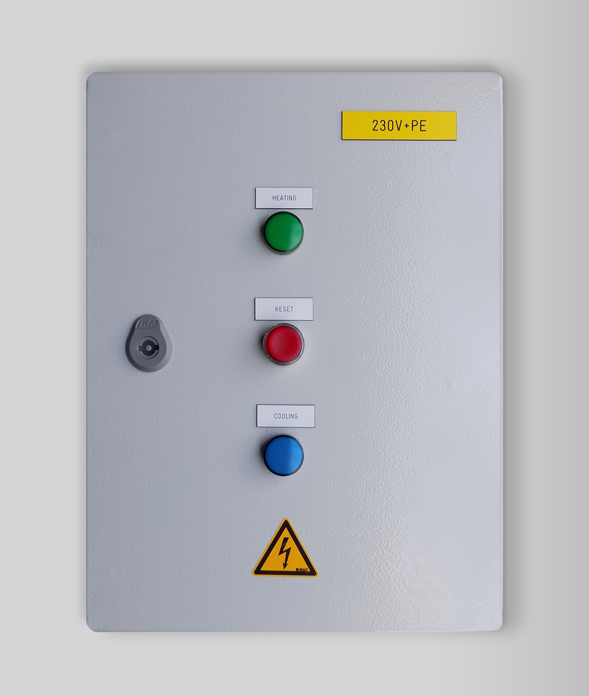
TECHNICAL DATA SAFETY & CONTROL BOX
| Nominal Voltage : | 220 / 110 V – 50 / 60 Hz |
| Purge time : | Variable 1 – 10 sec |
| Ignition time : | Variable 1 – 10 sec |
| Shut – off time : | Variable 1 – 10 sec |
| Start heat : | IN : 220 V / 110 V / 24 V / or / contact closed |
| Start cool : | IN : 220 V / 110 V / 24 V / or / contact closed |
| Heating running signal : | OUT : 220 V / 110 V / 24 V |
| Cooling running signal : | OUT : 220 V / 110 V / 24 V |
| Generated alarm : | OUT : 220 V / 110 V / 24 V |
| Indications : | GREEN : burner heating |
| RED : burner in alarm | |
| BLUE : burner cooling | |
| Dimensions and weight : | H 400 x W 300 x D 220 mm – 9 Kg |
A built in electronic device allows and simplifies the adjustment of the gas/air ratio.
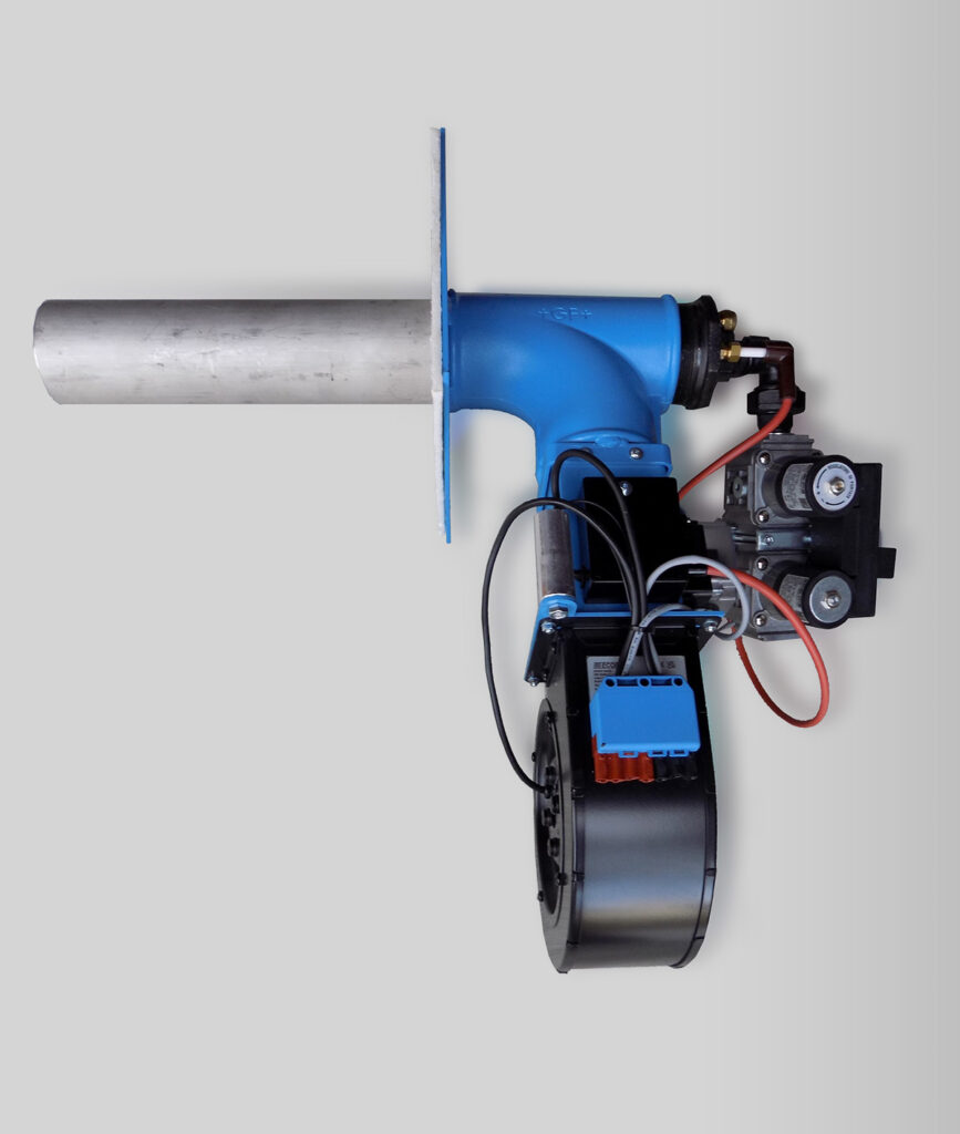
G7 – Replaces Replaces fan equipped burners up to 200 kWatt – ( Körting / Pennekamp tg1a – Weisshaupt etc. ) – Supports cooling.
MECHANICAL MOUNTING :
Burner :
Side mounted with a plate of 250 x 250 mm.
Fixing holes at 125 x 125 mm.
– The mounting plate and holes can be adapted to any dimension.
Safety & control box :
Mounted on supports that leave 40 mm between box and lehr wall.
GAS SUPPLY :
A stainless steel flexible tube links to the existing gas taps, all sizes.
– The burner runs on the existing type of gas and pressure.
ELECTRIC CONNECTIONS :
Burner :
Is linked to the Safety box with its own cable.
Safety & control box :
A cable links to the ‘Harting 10 pole female connector’, same pin layout.
– The electric connection can be modified to any existing situation
ELECTRIC SIGNALS :
Safety & control box :
Translates the signals between panel and burner. Accepts and sends back all signals from and to the panel.
– The power supply can be 110 or 220 V, 50 or 60 Hz.
– The control signals received can be 110, 220 V AC or 24 V DC.
– The control signals sent can be 110, 220 V AC or 24 V DC.
A built in electronic device allows and simplifies the adjustment of the gas/air ratio.
BURNERS :![]() G5
G5![]() –
–![]() G6B
G6B ![]() –
–![]() G7
G7
REALISATION & RESULTS
HOME ![]() –
– ![]() ELECTRIC HEATERS
ELECTRIC HEATERS ![]() –
– ![]() CONTACT
CONTACT